Hydraulic Withdrawal Sleeves: Models, Dimensions, and Specifications #
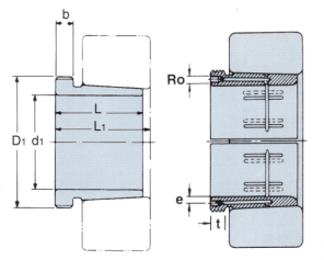
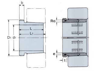
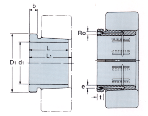
Hydraulic withdrawal sleeves are essential components for mounting and dismounting bearings with a tapered bore onto cylindrical shafts. This guide presents a structured overview of various hydraulic withdrawal sleeve models, their technical specifications, and dimensional data to assist in product selection and engineering design.
Key Product Series and Models #
AOH30 Series #
| Model | d1 (mm) | L (mm) | L1 (mm) | b (mm) | Ro | e (mm) | t (mm) | Thread | Nut No. | Weight (kg) |
|---|---|---|---|---|---|---|---|---|---|---|
| AOH3038 | 180 | 96 | 102 | 18 | M6 | 4.2 | 8 | Tr205*4 | HNL41 | 3.32 |
| AOH3040 | 190 | 102 | 108 | 19 | M6 | 4.2 | 8 | Tr215*4 | HNL43 | 3.80 |
| AOH3044 | 200 | 111 | 117 | 20 | G1/8 | 8.5 | 12 | Tr235*4 | HNL47 | 7.40 |
| … | … | … | … | … | … | … | … | … | … | … |
Note: Dimension L1 decreases as the hydraulic withdrawal sleeve is driven in during mounting. ‘M’ indicates metric thread, ‘Tr’ denotes 30° trapezoid thread with the digits representing the outside diameter and pitch.
AOH31 Series #
| Model | d1 (mm) | L (mm) | L1 (mm) | b (mm) | Ro | e (mm) | t (mm) | Thread | Nut No. | Weight (kg) |
|---|---|---|---|---|---|---|---|---|---|---|
| AOH3132 | 150 | 103 | 108 | 16 | M6 | 4.5 | 8 | M180*3 | AN36 | 3.21 |
| AOH3134 | 160 | 104 | 109 | 16 | M6 | 4.5 | 8 | M190*3 | AN38 | 3.40 |
| AOH3136 | 170 | 116 | 122 | 19 | M6 | 4.5 | 8 | M200*3 | AN40 | 4.22 |
| … | … | … | … | … | … | … | … | … | … | … |
Dimension L1 decreases as the sleeve is mounted. Thread types and sizes follow the same notation as above.
AOH32 Series #
| Model | d1 (mm) | L (mm) | L1 (mm) | b (mm) | Ro | e (mm) | t (mm) | Thread | Nut No. | Weight (kg) |
|---|---|---|---|---|---|---|---|---|---|---|
| AOH3232 | 150 | 124 | 130 | 20 | M6 | 4.5 | 8 | M180*3 | AN36 | 4.08 |
| AOH3234 | 160 | 134 | 140 | 24 | M6 | 4.5 | 8 | M190*3 | AN38 | 4.80 |
| AOH3236 | 170 | 140 | 146 | 24 | M6 | 4.5 | 8 | M200*3 | AN40 | 5.32 |
| … | … | … | … | … | … | … | … | … | … | … |
As with other series, L1 decreases during mounting. Thread and dimension notation remain consistent.
AOH39 Series #
| Model | d1 (mm) | L (mm) | L1 (mm) | b (mm) | Ro | e (mm) | t (mm) | Thread | Nut No. | Weight (kg) |
|---|---|---|---|---|---|---|---|---|---|---|
| AOH3944 | 200 | 77 | 83 | 16 | M8 | 7.5 | 12 | Tr230*4 | HN46 | 4.83 |
| AOH3948 | 220 | 77 | 83 | 16 | M8 | 7.5 | 12 | Tr250*4 | HN50 | 5.29 |
| AOH3952 | 240 | 94 | 100 | 18 | M8 | 7.5 | 12 | Tr270*4 | HN54 | 7.06 |
| … | … | … | … | … | … | … | … | … | … | … |
The L1 dimension decreases as the sleeve is installed. Thread and dimension notation are consistent with other series.
AOH240 Series #
| Model | d1 (mm) | L (mm) | L1 (mm) | b (mm) | Ro | e (mm) | t (mm) | Thread | Nut No. | Weight (kg) |
|---|---|---|---|---|---|---|---|---|---|---|
| AOH24044 | 200 | 138 | 152 | 20 | M6 | 8 | 8 | Tr230*4 | HN46 | 8.25 |
| AOH24048 | 220 | 138 | 153 | 20 | M6 | 8 | 8 | Tr250*4 | HN50 | 9.00 |
| AOH24052 | 240 | 162 | 178 | 22 | M6 | 8 | 8 | Tr270*4 | HN54 | 11.80 |
| … | … | … | … | … | … | … | … | … | … | … |
Dimension L1 decreases as the sleeve is driven in during mounting. Thread and dimension notation are consistent with the other series.
Notation and Technical Notes #
- L1: This dimension decreases as the hydraulic withdrawal sleeve is driven in during mounting.
- Thread Types: ‘M’ indicates metric thread, while ‘Tr’ refers to a 30° trapezoid thread. The digits following ‘Tr’ denote the outside diameter and pitch.
- Nut Numbers: Each sleeve model is paired with an appropriate withdrawal nut, referenced by its specific number.
For further details and the complete range of specifications, visit the Hydraulic Withdrawal Sleeves page.